WO2012128537A9 - Drill for implant surgery - Google Patents
Drill for implant surgery Download PDFInfo
- Publication number
- WO2012128537A9 WO2012128537A9 PCT/KR2012/001985 KR2012001985W WO2012128537A9 WO 2012128537 A9 WO2012128537 A9 WO 2012128537A9 KR 2012001985 W KR2012001985 W KR 2012001985W WO 2012128537 A9 WO2012128537 A9 WO 2012128537A9
- Authority
- WO
- WIPO (PCT)
- Prior art keywords
- drill
- implant
- bone
- upper portion
- blade
- Prior art date
Links
Images


Classifications
-
- A—HUMAN NECESSITIES
- A61—MEDICAL OR VETERINARY SCIENCE; HYGIENE
- A61C—DENTISTRY; APPARATUS OR METHODS FOR ORAL OR DENTAL HYGIENE
- A61C8/00—Means to be fixed to the jaw-bone for consolidating natural teeth or for fixing dental prostheses thereon; Dental implants; Implanting tools
- A61C8/0089—Implanting tools or instruments
-
- A—HUMAN NECESSITIES
- A61—MEDICAL OR VETERINARY SCIENCE; HYGIENE
- A61B—DIAGNOSIS; SURGERY; IDENTIFICATION
- A61B17/00—Surgical instruments, devices or methods, e.g. tourniquets
- A61B17/16—Bone cutting, breaking or removal means other than saws, e.g. Osteoclasts; Drills or chisels for bones; Trepans
- A61B17/1613—Component parts
- A61B17/1615—Drill bits, i.e. rotating tools extending from a handpiece to contact the worked material
-
- A—HUMAN NECESSITIES
- A61—MEDICAL OR VETERINARY SCIENCE; HYGIENE
- A61B—DIAGNOSIS; SURGERY; IDENTIFICATION
- A61B17/00—Surgical instruments, devices or methods, e.g. tourniquets
- A61B17/16—Bone cutting, breaking or removal means other than saws, e.g. Osteoclasts; Drills or chisels for bones; Trepans
- A61B17/1635—Bone cutting, breaking or removal means other than saws, e.g. Osteoclasts; Drills or chisels for bones; Trepans for grafts, harvesting or transplants
-
- A—HUMAN NECESSITIES
- A61—MEDICAL OR VETERINARY SCIENCE; HYGIENE
- A61B—DIAGNOSIS; SURGERY; IDENTIFICATION
- A61B17/00—Surgical instruments, devices or methods, e.g. tourniquets
- A61B17/16—Bone cutting, breaking or removal means other than saws, e.g. Osteoclasts; Drills or chisels for bones; Trepans
- A61B17/1662—Bone cutting, breaking or removal means other than saws, e.g. Osteoclasts; Drills or chisels for bones; Trepans for particular parts of the body
- A61B17/1673—Bone cutting, breaking or removal means other than saws, e.g. Osteoclasts; Drills or chisels for bones; Trepans for particular parts of the body for the jaw
-
- A—HUMAN NECESSITIES
- A61—MEDICAL OR VETERINARY SCIENCE; HYGIENE
- A61C—DENTISTRY; APPARATUS OR METHODS FOR ORAL OR DENTAL HYGIENE
- A61C3/00—Dental tools or instruments
- A61C3/02—Tooth drilling or cutting instruments; Instruments acting like a sandblast machine
-
- A—HUMAN NECESSITIES
- A61—MEDICAL OR VETERINARY SCIENCE; HYGIENE
- A61C—DENTISTRY; APPARATUS OR METHODS FOR ORAL OR DENTAL HYGIENE
- A61C8/00—Means to be fixed to the jaw-bone for consolidating natural teeth or for fixing dental prostheses thereon; Dental implants; Implanting tools
-
- A—HUMAN NECESSITIES
- A61—MEDICAL OR VETERINARY SCIENCE; HYGIENE
- A61B—DIAGNOSIS; SURGERY; IDENTIFICATION
- A61B17/00—Surgical instruments, devices or methods, e.g. tourniquets
- A61B17/16—Bone cutting, breaking or removal means other than saws, e.g. Osteoclasts; Drills or chisels for bones; Trepans
- A61B17/1637—Hollow drills or saws producing a curved cut, e.g. cylindrical
Definitions
- the present invention has a cylindrical pipe structure in which one side has a fastening structure with the handpiece for implant treatment, and the inside of which is empty, and there is a lower bone deletion blade and a side bone deletion blade so that the lower and side surfaces of the alveolar bone are changed by one drilling.
- the present invention relates to a drill for implantation, which is capable of forming an insertion hole of a tapered implant fixture that is easier to initially fix than a cylindrical implant when simultaneously cutting with cylindrical autogenous bone collection.
- a drill When performing an implant, a drill is generally used to drill a groove in the alveolar bone where the fixture is to be embedded.
- the diameter of the same length is small for implant placement.
- Korean Patent Publication No. 100759261 includes a drill body in which a bone accommodating part is accommodated to accommodate bone of an alveolar bone when a hole is drilled in the alveolar bone; A plurality of cutting edges formed at an end of the drill body to drill holes in the alveolar bone during rotation of the drill body; And an implant drill having a torsion angle formed on the outer circumference of the drill body and recessed from the surface of the drill body, wherein the implant drill comprises a plurality of bone discharge passages for guiding the discharge of the bone fragments of the alveolar bone generated when the alveolar bone is drilled.
- Korean Patent Publication No. 100985604 includes a cylindrical-shaped cutting part having a hollow, a stopper having a hollow to be detachable from an outer circumference of the cutting part, a stopper support part provided at one end of the cutting part, and a shank part provided at the stopper support part.
- the cutting portion includes a cutting edge, a cutting outlet formed in the lower portion of the cutting edge so that the hollow portion communicates with the outside through the side of the cutting portion, and the stopper has a longitudinal length exposing the cutting edge to a depth to be cut.
- It has a stopper support portion is disclosed a hollow drill for maxillary sinus lift, characterized in that to form a support jaw for preventing the stopper is pushed in the longitudinal direction,
- Korean Patent Publication No. 100946269 includes a punching body provided with a cutter for drilling alveolar bone at one end and a through hole formed at the other end; And a rod body coupled to the punching body so as to be accessible and spaced apart from one end of the punching body toward the through-hole of the punching body, the rod body adjusting the depth of drilling of the alveolar bone during the drilling operation.
- the implant for drilling the alveolar bone for the implant procedure a hollow tube-shaped drill body (10) formed with a cutting edge (12) at the end;
- a coupling body 20 coupled to a lower portion of the drill body 10 and mounted to a dental handpiece;
- a protruding member 30 inserted into the drill body 10 to elastically support and protrude outwardly;
- the drill body (10) is inserted into the alveolar bone to a certain depth so that the drill body (10) is mounted on the outer peripheral surface of the hollow tube-shaped stopper 40 is seated on the connecting body;
- a drill for implant treatment with a stopper characterized in that the contraction portion 42 is formed to enable the stopper 40 can be compressed by a certain height
- Korean Patent Publication No. 10-2009-0098428 discloses a cutting part including a cutting edge, a cutting outlet formed in the lower portion of the cutting edge so that the hollow part communicates with the outside through the cutting part side groove, and the stopper is intended to cut the cutting edge.
- the hollow drill for maxillary sinus elevation has a longitudinal length that exposes the depth to the depth, and the stopper support portion forms a support jaw for preventing the stopper from being pushed in the longitudinal direction.
- the Korean Registered Utility Model Publication No. 200323647 discloses a main body of a drill having a cylindrical shape having an opening with its bottom open, the periphery of the opening being composed of a basic blade having a repeating thread, and an opening inside the cylindrical part of the main body.
- An implant drill having a vertical blade upright to the side is disclosed,
- the publication No. 20-0230475 has a cylindrical upper and lower portions, and a plurality of through holes are formed on the side to form a fastening portion 150, and an end portion of the lower portion is a non-uniform surface when a hole is formed up to a set depth.
- a stopper (100) which enables a smooth contact with the upper surface of the tooth loss part and prevents the hole from being formed at a further depth;
- a plurality of fastening members 200 inserted into the fastening parts 150 formed on the side of the stopper 100 to fix the stopper 100 to the drill body 400.
- a drill stopper for an implant procedure to help form a hole of depth is disclosed, and the publication No.
- 20-0338095 discloses a dental stopper drill comprising a chuck coupling part, a shank part, and a drill part. It can be seen that there is disclosed a dental stopper drill in which a stopper is integrally formed between the drill portion and protrudes larger than the diameter of the shank portion and the drill portion so that the drill only digs a groove to a predetermined depth.
- implant implants have been formed by eliminating the alveolar bone by repeating several drills starting from a drill having the same diameter and having a smaller size for implant placement.
- the conventional drill has a problem that the number of drills used or the manufacturing cost is high, the problem that the durability is weak when repeated use is a problem to be solved by the present invention.
- the drill portion 20 has a cylindrical shape so that the diameter thereof becomes narrower toward the lower portion of the drill portion 20 so as to form an insertion hole of the tapered fixer at one time, and a space is formed therein, and spaced apart at a predetermined interval on the side. And a plurality of side through-holes 22 penetrating into the inner space, a plurality of side bone deletion blades 21 installed at one side edges of the plurality of side through-holes 22, and a sawtooth-shaped end portion. It is a problem solving means of the present invention to provide an implant drill consisting of a lower bone removal blade (30).
- the present invention minimizes the bone that is removed by the lateral bone removal blade and the vertical bone removal blade and the central hole, and can be easily detached, and the implant is completed by one drilling. It is possible to collect and reduce the use of expensive bone graft material, and by drilling only once, the procedure time can be drastically reduced, and the safety of the procedure can be secured, and the structure is simple. By enabling mass production, there is an effect that enables the standardization and economic dissemination of products.
- Figure 2 is a front view of the drill for implant treatment of the present invention
- FIG. 3 Another example of a drill for implant treatment of the present invention
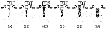
- Figure 4 is a state of use of the drill for implant treatment of the present invention
- the drill for the implant When the power is turned on by connecting the drill body to the handpiece of the surgical motor, the drill for the implant is rotated by the rotation of the driving drill and drilled using the lower part of the drill to the desired depth (see Fig. 4A), and remains in the center of the insertion hole.
- the protruding alveolar bones were removed with tweezers (see FIG. 4B) to form an implant, and an implant was performed.
- the present invention has a fastening structure with the handpiece for the implant procedure has a hollow cylindrical pipe structure on one side, there is a lower bone deletion blade and side bone deletion blade once Drilling of the lower and side of the alveolar bone at the same time through the drilling of the implant relates to an implant procedure drill that can form the insertion hole of the tapered implant fixture is easier to initial fixation than the cylindrical implant at the time of implantation.
- the present invention is a structure in which the drill portion 20 and the drill portion 20 is located at the lower portion of the drill connection portion 10, the drill connection portion 10 is installed on the upper side of the drill portion 11 ), A drill fixing groove 12 formed in the lower portion of the drill upper portion 11, and a drill connection body 13 installed in the lower portion of the drill fixing groove 12, the drill portion 20 is cylindrical The diameter becomes narrower toward the lower side, and a space part is formed inside, and penetrates the inner space part by a predetermined interval on the side (vertically penetrates the lower erased edge).
- the number of side penetrating portion 22 and the side bone deletion blade 21 of the present invention is 1 to 10, four is suitable.
- the present invention is an implant drill capable of collecting autologous bone at the same time by forming the insertion hole of the tapered fixer at a time with a small cutting resistance by removing only the marginal bone of the alveolar bone with the lower bone deletion blade and the side bone deletion blade.
- a basic drill is formed using a drill having a smaller diameter, and an alveolar bone is gradually removed using a drill having a larger diameter to form a fixture having a desired size. Planted,
- the drill 10-1 of the desired diameter is selected and coupled to the drill body (not shown), and then the drill body is connected to the shaft of the surgical motor (not shown) (inserted into the handpiece),
- the alveolar bone is drilled by fixing to the connected shaft, a circular groove is formed to remove the alveolar bone located inside the circular groove with a pincent, and then implants (fixtures) are implanted.
- the removed alveolar bone is an autogenous bone that can be used as an artificial bone for implant procedures.
- the drill for the implant of the desired diameter is selected, coupled to the drive drill body (not shown), and then the drill body connected to the axis of the surgical motor (not shown) (inserted into the handpiece), and then connected to the motor It is a device for drilling the alveolar bone fixed to the shaft.
- FIG. 1 is a drill overall view of the implant operation of the present invention
- Figure 2 drill front detail view of the implant operation of the present invention
- Figure 3 another example of the drill for the implant operation of the present invention
- Figure 4 the use state of the drill for the implant operation of the present invention
- 5 is a view illustrating a conventional implant drill using a drill connection part 10, an upper drill part 11, a drill fixing groove 12, a drill connection body 13, a drill part 20 and 120, and side bone deletion blades ( 21,121, side penetrations (22,122), the lower bone deletion blade (30,130) is shown.
- a drill for the implant operation of the present invention is a structure in which the drill portion 20 and the drill portion 20 is located in the lower portion of the drill connection portion 10,
- the drill connection part 10 is a drill upper portion 11 installed on one side in the upper portion, a drill fixing groove 12 formed in the lower portion of the drill upper portion 11, and a drill connection provided in the lower portion of the drill fixing groove 12 Body 13,
- the drill part 20 has a cylindrical shape, the diameter of which is narrowed toward the lower part, and a space part is formed therein, and a plurality of side penetrations penetrate the inner space part by a predetermined interval on the side (vertically penetrating the lower eraser blade).
- a plurality of side bone deletion blades 21 installed on one side edge of the plurality of side through-holes 22, and a serrated lower bone deletion blade 30 provided at the lower end portion
- Another implant treatment drill of the present invention has a structure in which the drill portion 120 and the drill portion 120 is located below the drill connection portion 10, as shown in Figure 3,
- the drill connection part 10 is a drill upper portion 11 installed on one side in the upper portion, a drill fixing groove 12 formed in the lower portion of the drill upper portion 11, and a drill connection provided in the lower portion of the drill fixing groove 12 Body 13,
- the drill portion 120 has a cylindrical shape, the diameter thereof becomes narrower toward the bottom, and a space portion is formed therein, and a plurality of inclined shapes penetrates the inner space portion by a predetermined interval on the side surface (work at the vertical of the lower erased edge).
- Side bent side (122) bent to the side (twisted), a plurality of inclined side bone deletion blades 121 are installed on one side edge of the plurality of side through portions 122, and the lower end It is a structure of the drill for the implant consisting of the tooth-shaped lower bone removal blade 130 installed in,
- One side has a fastening structure with the handpiece for implant treatment and has a hollow cylindrical pipe structure on one side.
- the lower and side bones have a lower bone and a side bone.
- the present invention relates to a drill for implantation, which is capable of forming an insertion hole of a tapered implant fixture that is easier to initially fix than a cylindrical implant with cylindrical autologous bone collection.
Abstract
Description
Claims (2)
- 임플란트 시술용 드릴에 있어서, In the drill for implant treatment,드릴연결부(10)와 상기 드릴연결부(10)의 하부에 드릴부(20)가 위치된 구조이며,Drill connection portion 10 and the drill portion 20 in the lower portion of the drill connection portion 10 is a structure that is located,상기 드릴연결부(10)은 상부에 일측에 설치된 드릴상부(11)와, 상기 드릴상부(11)의 하부에 형성된 드릴고정홈(12)과, 상기 드릴고정홈(12)의 하부에 설치된 드릴연결몸체(13)로 구성되고,The drill connection part 10 is a drill upper portion 11 installed on one side in the upper portion, a drill fixing groove 12 formed in the lower portion of the drill upper portion 11, and a drill connection provided in the lower portion of the drill fixing groove 12 Body 13,상기 드릴부(20)는 원통형상으로 하부로 갈수록 직경이 좁아지며 내부에는 공간부가 형성되어 있으며, 측면에는 일정간격 이격되어 내부공간부에 관통된 다수개의 측면관통부(22)와, 상기 다수개의 측면관통부(22)의 일측 테두리에 설치된 다수개의 측면골삭제날(21)와, 하부 끝단부에 설치된 톱니형상의 하부골삭제날(30)을 포함하여 구성되어 있음을 특징으로 하는 임플란트 시술용 드릴.The drill portion 20 has a cylindrical shape, the diameter thereof becomes narrower toward the bottom, and a space portion is formed therein, and a plurality of side through portions 22 penetrates the inner space portion by a predetermined interval on the side thereof, and the plurality of side portions. For implant treatment, characterized in that it comprises a plurality of side bone deletion blade 21 is installed on one side edge of the side through-hole 22, the lower bone deletion blade 30 of the serrated shape is provided in the lower end portion drill.
- 임플란트 시술용 드릴에 있어서, 드릴연결부(10)와 상기 드릴연결부(10)의 하부에 드릴부(120)가 위치된 구조이며,In the implant treatment drill, the drill connection portion 10 and the drill portion 120 is located in the lower portion of the drill connection portion 10 is a structure,상기 드릴연결부(10)는 상부에 일측에 설치된 드릴상부(11)와, 상기 드릴상부(11)의 하부에 형성된 드릴고정홈(12)과, 상기 드릴고정홈(12)의 하부에 설치된 드릴연결몸체(13)로 구성되고,The drill connection part 10 is a drill upper portion 11 installed on one side in the upper portion, a drill fixing groove 12 formed in the lower portion of the drill upper portion 11, and a drill connection provided in the lower portion of the drill fixing groove 12 Body 13,상기 드릴부(120)는 원통형상으로 하부로 갈수록 직경이 좁아지며 내부에는 공간부가 형성되어 있으며, 측면에는 일정간격 이격되어 내부공간부에 관통된 다수개의 기울어진 형상인 측면관통부(122)와, 상기 다수개의 측면관통부(122)의 일측 테두리에 설치된 다수개의 기울어진 형상의 측면골삭제날(121)와, 하부 끝단부에 설치된 톱니형상의 하부골삭제날(130)을 포함하여 구성되어 있음을 특징으로 하는 임플란트 시술용 드릴.The drill part 120 has a cylindrical shape, the diameter of which is narrowed toward the lower part, and a space part is formed therein, and a plurality of inclined side through parts 122 penetrating a predetermined distance on the side and penetrating the inner space part. It is configured to include a plurality of inclined side bone deletion blade 121 of the inclined shape installed on one side edge of the plurality of side through-holes 122, the serrated lower bone deletion blade 130 installed on the lower end Drill for implant treatment, characterized in that there is.
Priority Applications (9)
| Application Number | Priority Date | Filing Date | Title |
|---|---|---|---|
| JP2014500992A JP5969588B2 (en) | 2011-03-22 | 2012-03-20 | Implant surgery drill |
| CA2837457A CA2837457A1 (en) | 2011-03-22 | 2012-03-20 | Drill for implant surgery |
| ES12760317.3T ES2691632T3 (en) | 2011-03-22 | 2012-03-20 | Drill bit for implant surgery |
| PL12760317T PL2689743T3 (en) | 2011-03-22 | 2012-03-20 | Drill for implant surgery |
| EP12760317.3A EP2689743B1 (en) | 2011-03-22 | 2012-03-20 | Drill for implant surgery |
| RU2013146963/14A RU2013146963A (en) | 2011-03-22 | 2012-03-20 | IMPLANT SURGERY DRILL |
| US14/006,200 US10548693B2 (en) | 2011-03-22 | 2012-03-20 | Drill for implant surgery |
| DK12760317.3T DK2689743T3 (en) | 2011-03-22 | 2012-03-20 | Drill for implant surgery |
| CN201280019725.4A CN103648429A (en) | 2011-03-22 | 2012-03-20 | Drill for implant surgery |
Applications Claiming Priority (2)
| Application Number | Priority Date | Filing Date | Title |
|---|---|---|---|
| KR10-2011-0025532 | 2011-03-22 | ||
| KR1020110025532A KR101192662B1 (en) | 2011-03-22 | 2011-03-22 | Drill for an implant operation |
Publications (3)
| Publication Number | Publication Date |
|---|---|
| WO2012128537A2 WO2012128537A2 (en) | 2012-09-27 |
| WO2012128537A3 WO2012128537A3 (en) | 2013-01-03 |
| WO2012128537A9 true WO2012128537A9 (en) | 2013-02-14 |
Family
ID=46879888
Family Applications (1)
| Application Number | Title | Priority Date | Filing Date |
|---|---|---|---|
| PCT/KR2012/001985 WO2012128537A2 (en) | 2011-03-22 | 2012-03-20 | Drill for implant surgery |
Country Status (15)
| Country | Link |
|---|---|
| US (1) | US10548693B2 (en) |
| EP (1) | EP2689743B1 (en) |
| JP (1) | JP5969588B2 (en) |
| KR (1) | KR101192662B1 (en) |
| CN (1) | CN103648429A (en) |
| CA (1) | CA2837457A1 (en) |
| DK (1) | DK2689743T3 (en) |
| ES (1) | ES2691632T3 (en) |
| HU (1) | HUE040412T2 (en) |
| PL (1) | PL2689743T3 (en) |
| PT (1) | PT2689743T (en) |
| RU (1) | RU2013146963A (en) |
| TR (1) | TR201815665T4 (en) |
| TW (1) | TW201302163A (en) |
| WO (1) | WO2012128537A2 (en) |
Families Citing this family (15)
| Publication number | Priority date | Publication date | Assignee | Title |
|---|---|---|---|---|
| KR101192668B1 (en) * | 2011-03-25 | 2012-10-19 | 주식회사 이노바이오써지 | Maxillary Sinus elevator |
| US9974548B2 (en) * | 2014-09-09 | 2018-05-22 | Russo Surgical Tools, LLC | Surgical instrument for harvesting bone |
| JP7143079B2 (en) | 2015-05-06 | 2022-09-28 | カルティヒール(2009)リミティド | Optimized solid substrates, tools for use therewith and their use for promoting cell and tissue growth |
| KR101711613B1 (en) * | 2016-09-23 | 2017-03-02 | 김성주 | Drill for operating implant |
| KR101758803B1 (en) * | 2016-10-10 | 2017-07-17 | 주식회사 디오 | apparatus for implant drill |
| FR3062564A1 (en) * | 2017-02-07 | 2018-08-10 | Implants Diffusion International | SURGICAL FOREST WITH IRRIGATION HOLLOW RING. |
| WO2019135216A1 (en) * | 2018-01-02 | 2019-07-11 | Cartiheal (2009) Ltd. | Implantation tool and protocol for optimized solid substrates promoting cell and tissue growth |
| US20210052354A1 (en) * | 2018-02-13 | 2021-02-25 | Cameron Glenn Castle | Dental surgery method |
| CN109124788A (en) * | 2018-09-27 | 2019-01-04 | 上海交通大学医学院附属第九人民医院 | It is a kind of for pulling out the device of lower jaw impaction tooth bud |
| KR101921091B1 (en) * | 2018-10-16 | 2018-11-22 | 주식회사 디맥스 | Drill for implant surgery |
| US11246606B2 (en) * | 2019-08-12 | 2022-02-15 | Biomet 3I, Llc | Drill bit |
| KR102270227B1 (en) | 2020-11-23 | 2021-06-25 | 주식회사지온 | Low-speed rotary trephine tap drill for implant treatment |
| KR102609604B1 (en) * | 2021-03-03 | 2023-12-04 | (주)예스바이오테크 | Drill for operating implant |
| US11523834B1 (en) | 2022-06-20 | 2022-12-13 | University Of Utah Research Foundation | Cartilage and bone harvest and delivery system and methods |
| US11660194B1 (en) | 2022-06-20 | 2023-05-30 | University Of Utah Research Foundation | Cartilage and bone harvest and delivery system and methods |
Family Cites Families (35)
| Publication number | Priority date | Publication date | Assignee | Title |
|---|---|---|---|---|
| US1123730A (en) | 1912-09-13 | 1915-01-05 | Edwin J Greenfield | Annular bone-saw. |
| US1480730A (en) * | 1922-05-31 | 1924-01-15 | John A Lentz | Dental shoulder-cutting instrument |
| US3892117A (en) * | 1973-03-28 | 1975-07-01 | Milton E Nelson | Method of manufacturing lightweight dental drill for high-speed dental handpiece |
| US4431416A (en) * | 1982-04-29 | 1984-02-14 | A & L Investment Company | Endosseous dental implant system for overdenture retention, crown and bridge support |
| US4820156A (en) | 1986-12-29 | 1989-04-11 | Ross Systems Corporation | Trephine dental drill |
| IT1237496B (en) * | 1989-10-26 | 1993-06-08 | Giuseppe Vrespa | SCREW DEVICE FOR ANCHORING BONE PROSTHESES, METHOD FOR THE APPLICATION OF SUCH DEVICE AND RELATED EQUIPMENT |
| CN2097620U (en) * | 1991-07-11 | 1992-03-04 | 四川大学 | Surgical drill for artificial embedding tooth |
| US5366374A (en) * | 1993-05-18 | 1994-11-22 | Vlassis James M | Dental implant |
| EP0700272B1 (en) * | 1993-05-27 | 1999-01-07 | Howmedica Inc. | Flexible medullary reaming system |
| US5782636A (en) | 1996-10-02 | 1998-07-21 | Sulzer Calcitek Inc. | Bone contouring tool |
| US6039568A (en) * | 1998-06-02 | 2000-03-21 | Hinds; Kenneth F. | Tooth shaped dental implants |
| US5951561A (en) * | 1998-06-30 | 1999-09-14 | Smith & Nephew, Inc. | Minimally invasive intramedullary nail insertion instruments and method |
| ATE290824T1 (en) * | 1998-09-29 | 2005-04-15 | Zimmer Gmbh | HOLLOW MILLING CUTTER FOR TISSUE |
| US6517581B2 (en) * | 2001-01-25 | 2003-02-11 | Zimmer, Inc. | Method and apparatus for preparing a femur to receive a modular prosthetic femoral component |
| US6419490B1 (en) * | 2001-01-30 | 2002-07-16 | Arthur Kitchings Weathers, Jr. | Grooved intraosseous dental drill bit |
| KR200230475Y1 (en) | 2001-02-03 | 2001-07-03 | 권성오 | drill stopper for operating implant |
| KR200323647Y1 (en) | 2003-05-07 | 2003-08-19 | (주)이비아이 | Drill for implant surgery |
| US7074224B2 (en) * | 2003-06-25 | 2006-07-11 | Depuy Products, Inc. | Modular tapered reamer for bone preparation and associated method |
| KR200338095Y1 (en) | 2003-10-22 | 2004-01-13 | 주식회사 오스템 | Dental Stopper Drill |
| MXPA06008808A (en) | 2004-02-05 | 2007-01-23 | Bti I & D S L | Method and tools for low-speed milling without irrigation and with extraction and recovery of tissue particles. |
| ATE536142T1 (en) * | 2004-06-21 | 2011-12-15 | Straumann Holding Ag | METHOD FOR PRODUCING DISPOSABLE TURNTABLE CUTTING TOOLS AND DISPOSABLE TURNTABLE TOOL FOR DENTAL OR MEDICAL APPLICATIONS |
| US20060111724A1 (en) * | 2004-11-24 | 2006-05-25 | Yeung Research | Bone harvesting drill bit for oral surgery |
| US8672941B2 (en) * | 2005-02-02 | 2014-03-18 | Kensey Nash Bvf Technology Llc | Coring device for preserving living tissue |
| KR100759261B1 (en) * | 2007-01-15 | 2007-09-17 | 주식회사 메가젠 | Drill for operating implant |
| US8523866B2 (en) * | 2007-02-09 | 2013-09-03 | Christopher G. Sidebotham | Modular tapered hollow reamer for medical applications |
| JP2008295901A (en) * | 2007-06-01 | 2008-12-11 | Wakayoshi Seisakusho Co Ltd | Instrument for collecting excised bone |
| KR100940040B1 (en) * | 2007-11-26 | 2010-02-04 | 김수홍 | A tap drill for dental implant |
| KR100985604B1 (en) | 2008-03-14 | 2010-10-05 | 주식회사 덴티스 | A hollow drill for lateral sinus lift |
| US20090274996A1 (en) | 2008-05-05 | 2009-11-05 | Kenneth Miller | Bone cutting device and method of using same |
| KR100946269B1 (en) | 2008-07-29 | 2010-03-09 | 주식회사 메가젠임플란트 | Trephine Drill for Implant |
| DE102008029920B4 (en) * | 2008-06-24 | 2013-02-21 | Gebr. Brasseler Gmbh & Co. Kg | Trepan |
| KR100948616B1 (en) | 2008-07-15 | 2010-03-18 | 공용표 | Drill for implant with stopper |
| KR20100088640A (en) * | 2009-01-31 | 2010-08-10 | 이상직 | Sinus lift drill |
| USD644327S1 (en) * | 2010-09-02 | 2011-08-30 | Singh Pankaj P | Trephine drill |
| FR2964851B1 (en) * | 2010-09-21 | 2014-05-09 | Neolix | ENHANCED ENDODONTIC INSTRUMENT USING SLOT ALONG A CUTTING PORTION FOR PASSING A FLUID |
-
2011
- 2011-03-22 KR KR1020110025532A patent/KR101192662B1/en active IP Right Grant
-
2012
- 2012-03-20 TR TR2018/15665T patent/TR201815665T4/en unknown
- 2012-03-20 EP EP12760317.3A patent/EP2689743B1/en active Active
- 2012-03-20 CA CA2837457A patent/CA2837457A1/en not_active Abandoned
- 2012-03-20 PT PT12760317T patent/PT2689743T/en unknown
- 2012-03-20 JP JP2014500992A patent/JP5969588B2/en active Active
- 2012-03-20 HU HUE12760317A patent/HUE040412T2/en unknown
- 2012-03-20 PL PL12760317T patent/PL2689743T3/en unknown
- 2012-03-20 DK DK12760317.3T patent/DK2689743T3/en active
- 2012-03-20 WO PCT/KR2012/001985 patent/WO2012128537A2/en active Application Filing
- 2012-03-20 RU RU2013146963/14A patent/RU2013146963A/en not_active Application Discontinuation
- 2012-03-20 ES ES12760317.3T patent/ES2691632T3/en active Active
- 2012-03-20 US US14/006,200 patent/US10548693B2/en active Active
- 2012-03-20 CN CN201280019725.4A patent/CN103648429A/en active Pending
- 2012-03-21 TW TW101109646A patent/TW201302163A/en unknown
Also Published As
| Publication number | Publication date |
|---|---|
| US20140065573A1 (en) | 2014-03-06 |
| RU2013146963A (en) | 2015-04-27 |
| US10548693B2 (en) | 2020-02-04 |
| JP5969588B2 (en) | 2016-08-17 |
| EP2689743A4 (en) | 2014-10-08 |
| WO2012128537A3 (en) | 2013-01-03 |
| KR101192662B1 (en) | 2012-10-19 |
| HUE040412T2 (en) | 2019-03-28 |
| JP2014513606A (en) | 2014-06-05 |
| TR201815665T4 (en) | 2018-11-21 |
| EP2689743A2 (en) | 2014-01-29 |
| CA2837457A1 (en) | 2012-09-27 |
| DK2689743T3 (en) | 2018-12-03 |
| PT2689743T (en) | 2018-11-09 |
| WO2012128537A2 (en) | 2012-09-27 |
| ES2691632T3 (en) | 2018-11-28 |
| CN103648429A (en) | 2014-03-19 |
| EP2689743B1 (en) | 2018-08-08 |
| PL2689743T3 (en) | 2018-12-31 |
| TW201302163A (en) | 2013-01-16 |
| KR20120107796A (en) | 2012-10-04 |
Similar Documents
| Publication | Publication Date | Title |
|---|---|---|
| WO2012128537A9 (en) | Drill for implant surgery | |
| JP5562963B2 (en) | Apparatus and procedure for implanting dental implants | |
| WO2010128771A2 (en) | Unitary alveolar bone chisel and spreader osteotome for a dental implant | |
| WO2015133698A1 (en) | Dental implant fixture capable of easily receiving blood | |
| WO2010013900A2 (en) | Drill for implant | |
| WO2014200146A1 (en) | Endo pile for dental endodontic treatment | |
| WO2011046294A2 (en) | Drill for dental implant surgery | |
| WO2009157724A2 (en) | Safety drill assembly for performing the elevation of the periosteum in the maxillary sinus | |
| WO2007067105A1 (en) | A surgical tool for a dental implant procedure, a tool kit for a dental implant procedure and a method for making a dental implant | |
| WO2013126569A1 (en) | Dental drill bit | |
| WO2017131336A1 (en) | Dental flattening drill | |
| EP1900338B1 (en) | Positioning device for dental implant | |
| WO2018056552A1 (en) | Drill for implant procedure | |
| WO2011040687A1 (en) | Guide block for a dental implant procedure and guide block assembly, and implant procedural technique using same | |
| WO2011115339A1 (en) | Bur for alveolar bone | |
| WO2012134094A2 (en) | Safety subantral membrane lift capable of directly adjusting a subantral membrane to safely lift the subantral membrane in a desired direction by a desired distance, and operating method using same | |
| WO2024049278A1 (en) | Milling bur for implants | |
| WO2015012431A1 (en) | Impression cap coupleable to healing abutment | |
| WO2013154230A1 (en) | Dental bone collector | |
| EP2191785B1 (en) | Fixation pin | |
| WO2012128542A2 (en) | Bone carving tool for creating convex ridge for inner border of initial hole for placement of implant hole | |
| KR100929258B1 (en) | Medical Tapping Mechanism | |
| WO2011142631A2 (en) | Implant detector cover screw | |
| EP2332487A1 (en) | Holding tray | |
| WO2009136775A2 (en) | Pressure responsive drill |
Legal Events
| Date | Code | Title | Description |
|---|---|---|---|
| 121 | Ep: the epo has been informed by wipo that ep was designated in this application |
Ref document number: 12760317 Country of ref document: EP Kind code of ref document: A2 |
|
| NENP | Non-entry into the national phase |
Ref country code: DE |
|
| ENP | Entry into the national phase |
Ref document number: 2014500992 Country of ref document: JP Kind code of ref document: A |
|
| REEP | Request for entry into the european phase |
Ref document number: 2012760317 Country of ref document: EP |
|
| WWE | Wipo information: entry into national phase |
Ref document number: 2012760317 Country of ref document: EP |
|
| ENP | Entry into the national phase |
Ref document number: 2013146963 Country of ref document: RU Kind code of ref document: A |
|
| WWE | Wipo information: entry into national phase |
Ref document number: 14006200 Country of ref document: US |
|
| ENP | Entry into the national phase |
Ref document number: 2837457 Country of ref document: CA |