Due to the advantages of good frequency stability, very low distortion and easy tuning, the Wien bridge oscillator has become the most popular audio range signal generator circuit. Since this type of oscillator uses an RC feedback network, it can also be considered as an RC oscillator.
The main difference between a normal oscillator and a Wien bridge oscillator is that in a normal oscillator, a 180 degree phase shift is introduced in the amplifier stage and an additional 180 degree phase shift is introduced through the feedback network, thus obtaining a 360 degree or 0 degree phase shift around the loop to satisfy the Barkhausen criterion. However, in the case of the Wien bridge oscillator, the non-inverting amplifier used in the amplifier stage does not introduce any phase shift. Therefore, phase shifting through the feedback network is not required in order to satisfy the Barkhausen criterion.
Basic circuit of the Wien bridge oscillator
The Wien bridge oscillator produces a sine wave, which uses an RC network as the frequency-determining part of the circuit. The basic circuit of a Wien bridge oscillator with an amplification stage is shown in the following figure.
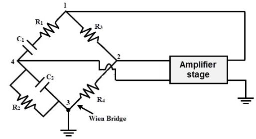
As can be seen from the above diagram, the output of the amplifier is applied between terminals 1 and 3, while the input of the amplifier stage is provided from terminals 2 and 4, so the amplifier output becomes the input voltage of the bridge, and the output of the bridge becomes the input voltage of the amplifier.

When the bridge is balanced, the input voltage of the amplifier becomes zero, and in order to produce continuous oscillation, the input of the amplifier must not disappear. Therefore, the bridge can be made unbalanced by adjusting the appropriate value of the resistor.
As mentioned above, the RC network is responsible for determining the frequency of the oscillator. the RC network consists of two frequency-sensitive arms, namely R1C1 in series and R2 and C2 in parallel, which is also known as the overrun hysteresis circuit.
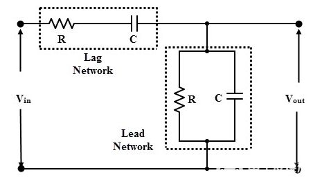
In a hysteresis circuit, the output voltage across the capacitor lags behind the input voltage by an angle between 0 and -90 degrees. In an overrun circuit, the output voltage across the resistor overruns the input voltage by an angle of 0 to 90 degrees.
At very low frequencies, the output voltage becomes zero because the series capacitor behaves as an open circuit, and at very high frequencies there is no output because the shunt capacitor acts as a short circuit path for the input voltage. Thus between these two extreme conditions, the output voltage reaches a maximum.
The resonant frequency is the frequency at which the output voltage is maximized. At this frequency, the feedback fraction K reaches 1/3 of its maximum value. the feedback is maximum when Xc = R, so that the resonant frequency is given by the following equation
f=1/2πRC
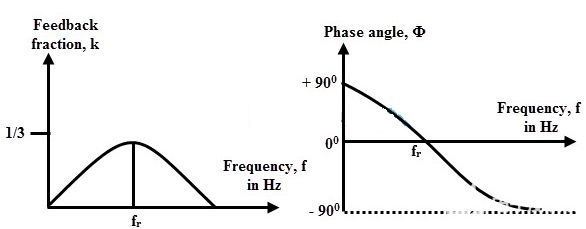
The above figure represents the output voltage at the resonant frequency. At the resonant frequency, the circuit has a zero phase shift and an attenuation of 1/3. Therefore, to maintain oscillation, the amplifier must have a gain greater than 3. By mounting two capacitors on the shaft and changing their values simultaneously, the Wien bridge oscillator can provide different frequency ranges.
Wien bridge oscillator using operational amplifiers
The figure below shows a widely used Wien bridge oscillator circuit. The operational amplifier is used in a non-inverting configuration and the feedback forms a voltage divider network. Resistors R1 and Rf form part of the feedback path, which determines or helps to adjust the amplifier gain.
The output of the op-amp is connected to the bridge as an input at points a and c, while the output of the bridge at points b and d is connected to the input of the op-amp.
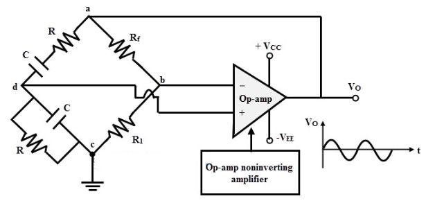
A portion of the amplifier output is fed back to the positive or non-inverting side of the amplifier through a voltage divider network (a series combination of resistors and capacitors). In addition, the second part of the amplifier is fed back to the inverting or negative terminal of the amplifier through an impedance of size 2R.
If the feedback network elements are properly selected, the phase shift of the signal input to the amplifier is zero at some frequency. Since the amplifier is non-inverting, it introduces zero phase shift plus zero phase shift of the feedback network, so the total phase shift becomes zero around the loop, hence the need for oscillation conditions.
Therefore, the Wien bridge oscillator is used as a sine wave generator, and its oscillation frequency is determined by the R and C components.
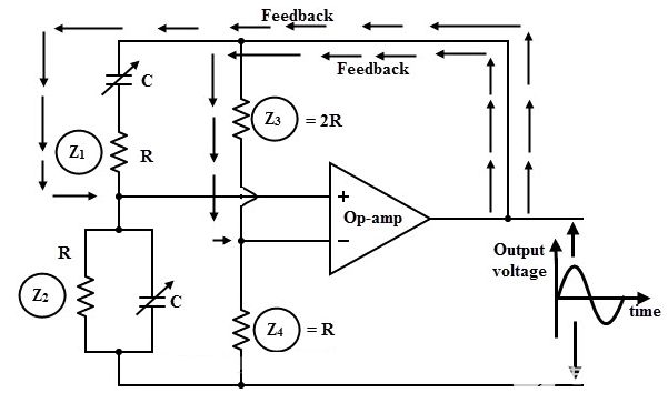
The gain of the operational amplifier is expressed as A = 1 + (Rf/R1).
As described above, the gain of an in-phase amplifier must be at least 3 to satisfy the Barkhausen criterion.
So, 1 + (Rf / R1) ≥ 3 => (Rf / R1) ≥ 2
Therefore, the ratio of the resistor Rf to R1 must be equal to or greater than 2. The oscillation frequency is given by the following equation
f=1/2πRC
Transistorized Wien bridge oscillator
The figure below shows a transistorized Wien bridge oscillator using a two-stage common emitter transistor amplifier, where each amplifier stage introduces a phase shift of 180 degrees, thus introducing a total phase shift of 360 degrees. The feedback bridge consists of RC series elements, RC parallel elements, and R3 and R4 resistors. The input to the bridge circuit is applied from the collector of transistor T2 through a coupling capacitor.
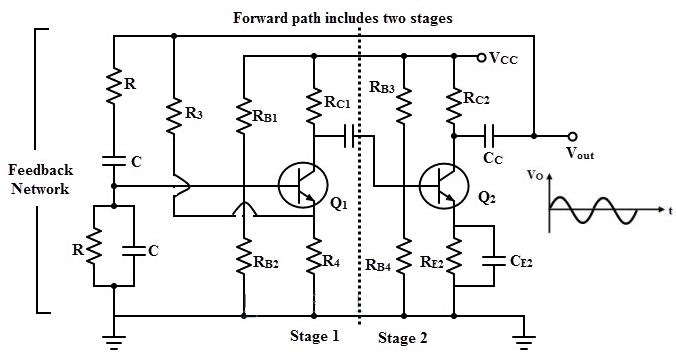
When a DC power supply is applied to the circuit, a noise signal is generated at the base of transistor T1 due to the movement of the charge carriers through the transistor and other circuit components. This voltage is amplified by gain A and produces an output voltage that differs 180 degrees from the input voltage.
This output voltage is applied as an input to the base terminal of the second transistor T2 and the voltage is multiplied by the gain of T2.
The amplified output of transistor T2 is 180 degrees out of phase with the output of T1. This output is fed back to transistor T1 through coupling capacitor C. Thus, this positive feedback generates oscillations over a wide frequency range when the Barkhausen condition is met.
Typically, the Wien bridge in the feedback network contains a single desired frequency of oscillation. The bridge is balanced at a frequency where the total phase shift is zero. The output of the two-stage transistor acts as the input to the feedback network, which is applied between the base and ground.
Feedback voltage Vf = (Vo×R4) / (R3+R4)
Automatic gain control of the Wien bridge
The gain must be self-regulating to achieve stability of the feedback oscillator. This is a form of automatic gain control (AGC). This can be achieved by simply connecting a Zener diode in parallel with resistor R3 in the feedback network. When the output signal reaches the Zener breakdown voltage, the Zener diode conducts, which in turn causes resistor R3 to short out.
This reduces the amplifier gain to 3, so that the total loop gain of 1 results in constant oscillation. Although this method of automatic gain control is simple, it is affected by the nonlinearity of the Zener diode and therefore the sine wave will be distorted.
Of course, another way to control gain is to use a JFET as a voltage controlled resistor in the negative feedback path. This gain control method produces a stable sinusoidal waveform compared to the Zener diode method. the JFET operates in an ohmic region with small or zero Vos.
As a result, the drain-source resistance increases as the gate voltage increases. When the JFET is placed in a negative feedback loop, automatic gain control is achieved through this voltage control resistor.
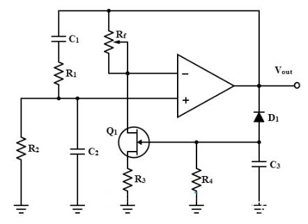
The above figure illustrates the automatic gain control of a JFET stabilized Wien bridge oscillator. In this circuit, the amplifier gain is controlled by components Rf, R3 and Q1. Depending on the gate voltage, the drain-source resistance is variable. This resistance is minimum at zero volts at the gate. At this point, the loop gain will be greater than one.
As the output voltage increases rapidly, the negative output signal is directed positively to the bias diode, so the capacitor charges to a negative voltage. This charging voltage increases the resistance of the JFET between the drain and source, which further reduces the amplifier gain.
The loop gain can be stabilized at the desired level by selecting the appropriate value of the feedback component.
Key Benefits
The overall gain of the Wien bridge oscillator is high due to the use of a secondary amplifier.
The oscillation frequency can be varied by changing the values of C1 and C2 or by using a variable resistor.
The Wien bridge produces very good sine waves with low distortion.
Frequency stability is good.
Since there is no inductor, there is no interference from external magnetic fields.
Main disadvantages
Two-stage amplifier type of Wien bridge oscillators require a larger number of components.
Cannot generate very high frequencies.
Summary
In short, the Wien bridge oscillator is a two-stage RC-coupled amplifier circuit with good stability at resonant frequencies, low distortion and very easy tuning, making it a popular circuit as an audio oscillator but with the phase output signal shifted very differently from previous phase-shifted RC oscillators.