
Related Manuals for Santak C1K


Summary of Contents for Santak C1K
- Page 1 Thank you for purchasing Santak product. Observe the warnings on the machine and manual strictly and properly keep the manual. Do not operate the UPS before read safety notes and operation instructions.
- Page 2 Solemn Declaration Monitoring code Declaration To protect your security and help you to buy real UPS of SANTAK, please note the following: 1. Make sure the registered trademarks is “ ” 、 2. SANTAK Electronic (Shenzhen) Co. Ltd. has never authorize other companies to product UPS of Santak in China 3.
- Page 3 UPS is completely shut down. Or else, the output terminal may carry live voltage, thus present- ing electric shock risk. 3. Please use fitting and accessories were appointed by SANTAK. 4. To meet the requirement of EMC, the length of the output should be less than 10m.
- Page 4 A. Remove watches, rings, or other metal object from the hands; B. Use tools with insulated handles; C. Wear rubber gloves and boots; D. Do not lay tools or metal parts on top of batteries; E. Disconnect the load before operate the terminal of battery. 5.
-
Page 5: Table Of Contents
Safety notes Introduction Product Description 2.1 System Type and Configuration 2.2 The Appearance of the UPS 2.3 Operating Principle Installation 3.1 Unpacking Inspection 3.2 Installation Notes 3.3 Cable Connection 3.3.1 Connecting Input and Output Cables 3.3.2 Operation Procedure of External Battery for Long Backup Time UPS 3.3.3 Connecting Communication Cable Operation... - Page 6 Maintenance 5.1 Battery Maintenance 5.2 Checking UPS function Troubleshooting Specifications 7.1 Electrical 7.2 Mechanical 7.3 Environmental 7.4 EMC 7.5 Safety 7.6 Industry Standard Warranty...
-
Page 7: Introduction
Introduction Description of Commonly Used Symbols Some or all of the following symbols may be used in this manual and may appear in your application process. Therefore, all users should read the form carefully and thoroughly. Symbol & Description Symbol Description Caution, danger Danger electric shock... -
Page 8: Product Description
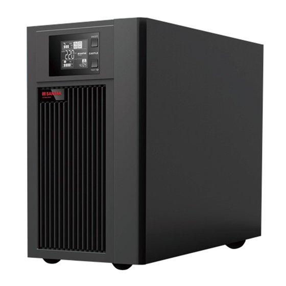
Product Description The On-Line-Series is an uninterruptible power supply incorporating double-converter technology. It provides perfect protection specifically for strict load. The double-converter principle eliminates all mains power disturbances. A rectifier con- verts the alternating current from the socket outlet to direct current. This direct current charges the batteries and powers the inverter. -
Page 9: The Appearance Of The Ups
Product Description The Appearance of the UPS Computer Interface Intelligent Slot Surge Protection Output Breaker Input External Battery Connector Figure 2-1 The rear panel of C1KS Intelligent Slot Computer Interface Surge Protection Output External Battery Connector Breaker Input Figure 2-2 The rear panel of C2KS... -
Page 10: Operating Principle
Product Description Intelligent Slot Computer Interface Surge Protection Output Terminal Block Cover Terminal Block External Battery Breaker Connector Input Figure 2-3 The rear panel of C3KS : The appearances above make example with the long backup time, the Note standard corresponding is without the “External Battery connector”. Operating Principle Bypass Output... - Page 11 Product Description Input filter: Perform a filter for input .It provides clean AC power to the UPS. AC/DC converter: In Normal mode, it converts the AC input power to regulated DC power. DC/DC converter: Raises the DC Voltage from the battery system to the optimum operating voltage for the inverter when the UPS operates in Battery mode.
-
Page 12: Installation
Installation Unpacking Inspection Open the packing box of UPS and take it out, visually examine the unit for transit damage. Check against the accessory lists that the accessories of the UPS are present. (Refer to Table 3-1). 3. If the UPS arrives damaged, or there is any missing accessory, please contact the distributor immediately. -
Page 13: Cable Connection
If the UPS is connected via the power cable, please use a proper socket with protection against electric current, and pay attention to the capacity of the socket: over 10A for C1K(S) , over 16A for C2K(S) and C3K(S). The wiring configuration is shown in the following diagram. - Page 14 Installation Figure 3-2 Connection method of output for C1K(S)~C3K(S) Apart from using the socket for output, C3K(S) has the terminal block available for output as well when the output current over 10A recommended. The wring configuration is shown in the following diagram.
-
Page 15: Operation Procedure Of External Battery For Long Backup Time Ups
Installation Figure 3-3 Connection method of terminal block for 3K(S) Caution: Do not connect the loads with terminal block by the personal without quali- fied training. 3.3.2 Operation Procedure of External Battery for Long Backup Time UPS The battery connection procedure is very important. Any incompliance may result in the risk of electric shock. -
Page 16: Connecting Communication Cable
Computer Communication cable computer interface: The type of signals, serial command (RS232), is provided by the UPS to communicate with a host computer. User can use WinPower software(download from the web of santak) to monitor the UPS through the port. - Page 17 Installation Alternative connection of communication Intelligent slot Intelligent Slot: It is designed for installing the AS400 card, SNMP card and CMC card. You can choose for one of them to installed a-AS400: You can utilize AS400’s monitor function to manage the power supply directly.
-
Page 18: Operation
Operation Introduction of Display Panel : 3# Load/battery capacity indicator : 4# Load/battery capacity indicator : 2# Load/battery capacity indicator : 5# Load/battery capacity indicator : : 6# Load/battery capacity indicator 1# Fault indicator : 7# Bypass indicator : 8# Utility power indicator :... -
Page 19: Operation Mode
Operation 3. LED indicators The LEDs contains Fault indicator, Load/battery capacity indicator, Bypass indicator, utility power indicator, Inverter indicator, Battery indicator. Table 4-1 Description of indicators Description Indicator Color When the indicator on, it shows that the UPS in Fault indicator abnormal condition. - Page 20 Operation 1. If the utility power indicator blinks, it indicates that there are problems with reversed polarity (L, N) of site wiring or disconnect with ground that may result in shock hazard. UPS is still working in normal mode. If the battery indicator is turn on at the same time, it shows that the voltage or frequency of the utility power is out of the normal input range of the UPS.
-
Page 21: Battery Mode
Operation 4.2.2 Battery mode In battery mode the display on the front panel is shown in the following diagram. The battery indicator and the inverter indicator are turn on. If the utility power indicator blinks at the same time, it shows that the utility power is abnormal. -
Page 22: Bypass Mode
Operation 4.2.3 Bypass mode When operating in bypass mode set up through WinPower software, the display on the front panel is show in the following diagram. The utility power indicator and the bypass indicator are turn on. The load/battery ca- pacity indicator will be turned on in accordance with the load capacity connected. - Page 23 Operation 1. Turning on the UPS The operation of turning on the UPS contains: turning on with utility power and turning on without utility power. Turning on with utility power: Connect the mains input to the UPS, press and hold the ON/ OFF button for 1 second until the buzzer beeps.
-
Page 24: Conducting Battery Self-Diagnosis
Operation Completely power down the UPS from Battery mode Press the “ON/OFF” button persistently for more than 1 sec ond to power off the UPS. When being powered off, the UPS will start self-diagnosis and all the load/battery capacity indi cators will be turn on and off one after another. -
Page 25: Audible Alarm And Led Indication Of Ups Operating Status And Faults
Operation 4.3.3 Audible alarm and LED indication of UPS operating status and faults LED indicators Audible Operating status alarm ● ● ● 0%--35% load None ● ● ● ● 36%--55% load None Normal ● ● ● ● ● 56%--75% load None mode ●... -
Page 26: Maintenance
Maintenance Battery Maintenance The battery is key component of the UPS. The battery life depends on the ambient temperature, charge and discharge times. High ambient temperature and deep dis- charge will shorten the battery life. Sealed maintenance-free lead –acid battery be used in the standard. When being connected to the utility power whether the UPS has been turned on or not, the UPS keeps charging the battery and also offers the protective function of charg- ing and discharging. -
Page 27: Checking Ups Function
Maintenance Checking UPS function Every time when conducting field maintenance, please check the regular func- tion of the UPS, including: 1. Check the operation status of the UPS If the main voltage is within the specifications, the UPS should operate in normal mode;... -
Page 28: Troubleshooting
Troubleshooting In the event of an UPS fault, shoot the trouble according to Table 6-1. If the fault still persists, please contact the customer service center. Table 6-1 UPS troubleshooting Problem Possible cause solution The #1 Fault LED and #6 Internal overheat Ensure that the UPS is not overloaded and the ventilation LED are on, the buzzer beeps... - Page 29 Troubleshooting Problem Possible cause solution The #1 Fault LED and #2 The UPS output is short Turn off the UPS. Remove all loads. Ensure that the loads LED and #5 are on, the buzzer circuited are not failed or has no internal short before turn on it beeps continuously again.
-
Page 30: Specifications
Specifications Electrical Model C1KS C2KS C3KS Rating 1kVA/800W 2kVA/1600W 3kVA/2400W Input system Single phase & earth ground Rated voltage 220VAC Voltage range 115VAC~300VAC Input Frequency 50Hz Power factor 0.98 Voltage range of 80VAC×(1±5%) ~285VAC×(1±5%) bypass Output system Single phase & earth ground Rated voltage 220VAC Power factor... -
Page 31: Mechanical
Specifications Mechanical Model W*H*D(mm) Weight(kg) 12 kg 145×220×355 C1KS 6.5 kg 145×220×355 23 kg 190×318×383 C2KS 10.5 kg 190×318×383 28 kg 190×318×433 C3KS 11.5 kg 190×318×433 Environmental Item Normal range 0? ~40? ℃ ℃ Ambient temperature ~90%(No condensation) Environment humidity Lower than 1000m: no derating Altitude Over 1000m :1% derating for every 100m rise... -
Page 32: Warranty
Warranty SANTAK its products to be offered free warranty service for three years from the date of purchase To obtain service under warranty via an valid guarantee offered by dealers; To obtain service under warranty via serial number. In case of UPS fault, please contact local Santak service center and dealer. The trans portation charges shall be borne by the buyer within the warranty period of 3 years.