Yikes! Invalid device signature
It sometimes happens: you are trying to program an Attiny and you get an error. There might be many causes for errors: you may not have selected the proper board, your programmer might be rotten, you did something wrong or the connections of your programmer are not correct, but sometimes it can be caused by the wrong bits being set in your Attiny: e.g. you set pin 1 (reset) to be an I/O pin. That makes it impossible to program it with ISP, or you set the wrong oscillator. For these cases a High Voltage programmer can be of help.
It happened to me when i was trying to ‘burn the bootloader’ on my attiny85 (there is no bootlaoder for the attiny 85 but this means setting the fuses). My computer’s memory was kinda full when I was busy and suddenly something crashed and I got the dreaded error message Yikes! Invalid device signature. As said, often this is because of a bad connection, but another chip didnt have that problem so I knew something was very wrong.
Time to build a High Voltage Programmer
Below you will see such a circuit. It is fairly simple: 6 resistors, a transistor a DIL foot and a 12 Volt source from somewhere. As I didn’t expect to have to use the HVP often, I opted for a battery, but as I displaced it, I ended up using a 75 euroct 5 to 12 Volt converter that I plugged in.

And this is an easy way to build it on stripboard.


I have built it such that it sticks into the D8-D13,ground header of an Arduino UNO. The only thing you need to do is to attach a 12 Volt battery, or an other 12 Volt source.
There are various programs that can reset the bits back to factory setting. Below you will find 2 of them that all go back to some initial work by Jos Keyzer.
The first one expects you to set the factory bits in the program depending on the chip you are using, the 2nd program actually reads what chip you are using, so I ended up using that one. Both programs start after you send a random character to the serial port.
 Well, as it turned out, my fuses were set for E4 and DF. That means that the Attiny was expecting a 128 kHz oscillator signal. No idea how that happened as I have disabled that choice in my menu so I guess it happened coz of my computer crashing. We will never know, but the HVP set it back to factory settings: i.e. 8MHz internal oscillator with a prescaler of 8.
After that, I could just program my Attiny again.
In principle this programmer can be used for Attiny 15 and 12 as well, but as far as I recall they have some wires crossed, so you would need to make a hardware change (connect the D12 resistor to pin 3 instead of pin2), but Attiny 13/25/45/85 should work like a charm.
It can also be done on the 24/44/84 series, but they need a 14 pins DIL:

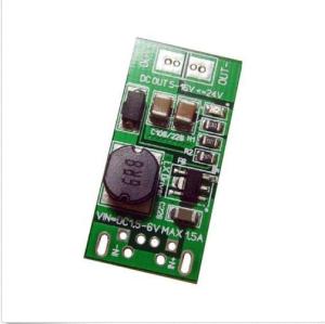 Should you need a cheap 12 Volt source, consider this 5 to 12 Volt converter
Program:
// AVR High-voltage Serial Programmer
// Originally created by Paul Willoughby 03/20/2010
// http://www.rickety.us/2010/03/arduino-avr-high-voltage-serial-programmer/
// Inspired by Jeff Keyzer http://mightyohm.com
// Serial Programming routines from ATtiny25/45/85 datasheet

// Desired fuse configuration
#define  HFUSE  0xDF   // Defaults for ATtiny25/45/85
#define  LFUSE  0x62
// For Attiny13 use
// #define HFUSE 0xFF
// #define LFUSE 0x6A


#define  RST     13    // Output to level shifter for !RESET from transistor to Pin 1
#define  CLKOUT  12    // Connect to Serial Clock Input (SCI) Pin 2
#define  DATAIN  11    // Connect to Serial Data Output (SDO) Pin 7
#define  INSTOUT 10    // Connect to Serial Instruction Input (SII) Pin 6
#define  DATAOUT  9    // Connect to Serial Data Input (SDI) Pin 5
#define  VCC      8    // Connect to VCC Pin 8

int inByte = 0;         // incoming serial byte Computer
int inData = 0;         // incoming serial byte AVR

void setup()
{
  // Set up control lines for HV parallel programming
  pinMode(VCC, OUTPUT);
  pinMode(RST, OUTPUT);
  pinMode(DATAOUT, OUTPUT);
  pinMode(INSTOUT, OUTPUT);
  pinMode(CLKOUT, OUTPUT);
  pinMode(DATAIN, OUTPUT);  // configured as input when in programming mode

  // Initialize output pins as needed
  digitalWrite(RST, HIGH);  // Level shifter is inverting, this shuts off 12V

  // start serial port at 9600 bps:
  Serial.begin(9600);

  establishContact();  // send a byte to establish contact until receiver responds

}


void loop()
{
  // if we get a valid byte, run:
  if (Serial.available() > 0) {
    // get incoming byte:
    inByte = Serial.read();
    Serial.println(byte(inByte));
    Serial.println("Entering programming Mode\n");

    // Initialize pins to enter programming mode
    pinMode(DATAIN, OUTPUT);  //Temporary
    digitalWrite(DATAOUT, LOW);
    digitalWrite(INSTOUT, LOW);
    digitalWrite(DATAIN, LOW);
    digitalWrite(RST, HIGH);  // Level shifter is inverting, this shuts off 12V

    // Enter High-voltage Serial programming mode
    digitalWrite(VCC, HIGH);  // Apply VCC to start programming process
    delayMicroseconds(20);
    digitalWrite(RST, LOW);   //Turn on 12v
    delayMicroseconds(10);
    pinMode(DATAIN, INPUT);   //Release DATAIN
    delayMicroseconds(300);

    //Programming mode

    readFuses();

    //Write hfuse
    Serial.println("Writing hfuse");
    shiftOut2(DATAOUT, INSTOUT, CLKOUT, MSBFIRST, 0x40, 0x4C);
    shiftOut2(DATAOUT, INSTOUT, CLKOUT, MSBFIRST, HFUSE, 0x2C);
    shiftOut2(DATAOUT, INSTOUT, CLKOUT, MSBFIRST, 0x00, 0x74);
    shiftOut2(DATAOUT, INSTOUT, CLKOUT, MSBFIRST, 0x00, 0x7C);

    //Write lfuse
    Serial.println("Writing lfuse\n");
    shiftOut2(DATAOUT, INSTOUT, CLKOUT, MSBFIRST, 0x40, 0x4C);
    shiftOut2(DATAOUT, INSTOUT, CLKOUT, MSBFIRST, LFUSE, 0x2C);
    shiftOut2(DATAOUT, INSTOUT, CLKOUT, MSBFIRST, 0x00, 0x64);
    shiftOut2(DATAOUT, INSTOUT, CLKOUT, MSBFIRST, 0x00, 0x6C);

    readFuses();

    Serial.println("Exiting programming Mode\n");
    digitalWrite(CLKOUT, LOW);
    digitalWrite(VCC, LOW);
    digitalWrite(RST, HIGH);   //Turn off 12v
  }
}


void establishContact() {
  while (Serial.available() <= 0) {
    Serial.println("Enter a character to continue");   // send an initial string
    delay(1000);
  }
}

int shiftOut2(uint8_t dataPin, uint8_t dataPin1, uint8_t clockPin, uint8_t bitOrder, byte val, byte val1)
{
	int i;
        int inBits = 0;
        //Wait until DATAIN goes high
        while (!digitalRead(DATAIN));

        //Start bit
        digitalWrite(DATAOUT, LOW);
        digitalWrite(INSTOUT, LOW);
        digitalWrite(clockPin, HIGH);
  	digitalWrite(clockPin, LOW);

	for (i = 0; i < 8; i++)  {

		if (bitOrder == LSBFIRST) {
			digitalWrite(dataPin, !!(val & (1 << i)));
                        digitalWrite(dataPin1, !!(val1 & (1 << i)));
                }
		else {
			digitalWrite(dataPin, !!(val & (1 << (7 - i))));
                        digitalWrite(dataPin1, !!(val1 & (1 << (7 - i))));
                }
                inBits <<=1;
                inBits |= digitalRead(DATAIN);
                digitalWrite(clockPin, HIGH);
		digitalWrite(clockPin, LOW);

	}


        //End bits
        digitalWrite(DATAOUT, LOW);
        digitalWrite(INSTOUT, LOW);
        digitalWrite(clockPin, HIGH);
        digitalWrite(clockPin, LOW);
        digitalWrite(clockPin, HIGH);
        digitalWrite(clockPin, LOW);

        return inBits;
}

void readFuses(){
     //Read lfuse
    shiftOut2(DATAOUT, INSTOUT, CLKOUT, MSBFIRST, 0x04, 0x4C);
    shiftOut2(DATAOUT, INSTOUT, CLKOUT, MSBFIRST, 0x00, 0x68);
    inData = shiftOut2(DATAOUT, INSTOUT, CLKOUT, MSBFIRST, 0x00, 0x6C);
    Serial.print("lfuse reads as ");
    Serial.println(inData, HEX);

    //Read hfuse
    shiftOut2(DATAOUT, INSTOUT, CLKOUT, MSBFIRST, 0x04, 0x4C);
    shiftOut2(DATAOUT, INSTOUT, CLKOUT, MSBFIRST, 0x00, 0x7A);
    inData = shiftOut2(DATAOUT, INSTOUT, CLKOUT, MSBFIRST, 0x00, 0x7E);
    Serial.print("hfuse reads as ");
    Serial.println(inData, HEX);

    //Read efuse
    shiftOut2(DATAOUT, INSTOUT, CLKOUT, MSBFIRST, 0x04, 0x4C);
    shiftOut2(DATAOUT, INSTOUT, CLKOUT, MSBFIRST, 0x00, 0x6A);
    inData = shiftOut2(DATAOUT, INSTOUT, CLKOUT, MSBFIRST, 0x00, 0x6E);
    Serial.print("efuse reads as ");
    Serial.println(inData, HEX);
    Serial.println();
}
An other program is:
// AVR High-voltage Serial Fuse Reprogrammer
// Adapted from code and design by Paul Willoughby 03/20/2010
// http://www.rickety.us/2010/03/arduino-avr-high-voltage-serial-programmer/
// Fuse Calc:
// http://www.engbedded.com/fusecalc/
#define RST 13 // Output to level shifter for !RESET from transistor
#define SCI 12 // Target Clock Input
#define SDO 11 // Target Data Output
#define SII 10 // Target Instruction Input
#define SDI 9 // Target Data Input
#define VCC 8 // Target VCC
#define HFUSE 0x747C
#define LFUSE 0x646C
#define EFUSE 0x666E
// Define ATTiny series signatures
#define ATTINY13 0x9007 // L: 0x6A, H: 0xFF 8 pin
#define ATTINY24 0x910B // L: 0x62, H: 0xDF, E: 0xFF 14 pin
#define ATTINY25 0x9108 // L: 0x62, H: 0xDF, E: 0xFF 8 pin
#define ATTINY44 0x9207 // L: 0x62, H: 0xDF, E: 0xFFF 14 pin
#define ATTINY45 0x9206 // L: 0x62, H: 0xDF, E: 0xFF 8 pin
#define ATTINY84 0x930C // L: 0x62, H: 0xDF, E: 0xFFF 14 pin
#define ATTINY85 0x930B // L: 0x62, H: 0xDF, E: 0xFF 8 pin
void setup() {
pinMode(VCC, OUTPUT);
pinMode(RST, OUTPUT);
pinMode(SDI, OUTPUT);
pinMode(SII, OUTPUT);
pinMode(SCI, OUTPUT);
pinMode(SDO, OUTPUT); // Configured as input when in programming mode
digitalWrite(RST, HIGH); // Level shifter is inverting, this shuts off 12V
Serial.begin(19200);
}
void loop() {
if (Serial.available() > 0) {
Serial.read();
pinMode(SDO, OUTPUT); // Set SDO to output
digitalWrite(SDI, LOW);
digitalWrite(SII, LOW);
digitalWrite(SDO, LOW);
digitalWrite(RST, HIGH); // 12v Off
digitalWrite(VCC, HIGH); // Vcc On
delayMicroseconds(20);
digitalWrite(RST, LOW); // 12v On
delayMicroseconds(10);
pinMode(SDO, INPUT); // Set SDO to input
delayMicroseconds(300);
unsigned int sig = readSignature();
Serial.print("Signature is: ");
Serial.println(sig, HEX);
readFuses();
if (sig == ATTINY13) {
writeFuse(LFUSE, 0x6A);
writeFuse(HFUSE, 0xFF);
} else if (sig == ATTINY24 || sig == ATTINY44 || sig == ATTINY84 ||
sig == ATTINY25 || sig == ATTINY45 || sig == ATTINY85) {
writeFuse(LFUSE, 0x62);
writeFuse(HFUSE, 0xDF);
writeFuse(EFUSE, 0xFF);
}
readFuses();
digitalWrite(SCI, LOW);
digitalWrite(VCC, LOW); // Vcc Off
digitalWrite(RST, HIGH); // 12v Off
}
}
byte shiftOut (byte val1, byte val2) {
int inBits = 0;
//Wait until SDO goes high
while (!digitalRead(SDO))
;
unsigned int dout = (unsigned int) val1 << 2;
unsigned int iout = (unsigned int) val2 << 2;
for (int ii = 10; ii >= 0; ii--) {
digitalWrite(SDI, !!(dout & (1 << ii)));
digitalWrite(SII, !!(iout & (1 << ii)));
inBits <<= 1; inBits |= digitalRead(SDO);
digitalWrite(SCI, HIGH);
digitalWrite(SCI, LOW);
}
return inBits >> 2;
}
void writeFuse (unsigned int fuse, byte val) {
shiftOut(0x40, 0x4C);
shiftOut( val, 0x2C);
shiftOut(0x00, (byte) (fuse >> 8));
shiftOut(0x00, (byte) fuse);
}
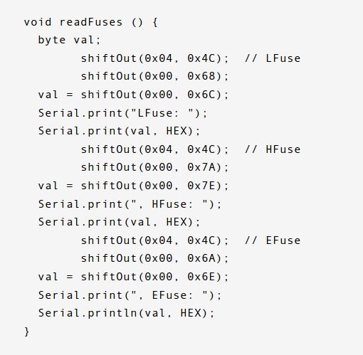
void readFuses () {
byte val;
shiftOut(0x04, 0x4C); // LFuse
shiftOut(0x00, 0x68);
val = shiftOut(0x00, 0x6C);
Serial.print("LFuse "); // this line may show up corrupted in some browsers it is a Serial.print("LFuse: ");
Serial.print(val, HEX);
shiftOut(0x04, 0x4C); // HFuse
shiftOut(0x00, 0x7A);
val = shiftOut(0x00, 0x7E);
Serial.print(", HFuse: ");
Serial.print(val, HEX);
shiftOut(0x04, 0x4C); // EFuse
shiftOut(0x00, 0x6A);
val = shiftOut(0x00, 0x6E);
Serial.print(", EFuse: ");
Serial.println(val, HEX);
}
unsigned int readSignature () {
unsigned int sig = 0;
byte val;
for (int ii = 1; ii < 3; ii++) {
shiftOut(0x08, 0x4C);
shiftOut( ii, 0x0C);
shiftOut(0x00, 0x68);
val = shiftOut(0x00, 0x6C);
sig = (sig << 8) + val;
}
return sig;
}
---
One may find this article interesting as well
If you want to see how this board (in a skightly more luxurious build) is used in practice you may want to check a youtube video by Ralph Bacon.

Very nice. BTW, Have a look at what Jenna did for Digispark (google “micronucleus”). Brilliant. Once the fuses are set, just load (as in flash) a new bootloader through a user program.
Thanks Jeroen. This one you mean I guess: https://github.com/Bluebie/micronucleus
Naj (no-yes). It has been integrated in the “official” (I guess) micronucleus git. https://github.com/micronucleus/micronucleus/tree/v1.11 But then again, not carried over to the 2.0 release. Confused.
I might have come across that one as well. will have a better look… when i have time 🙂
There is one part that confuses me a bit I must confess, which has to do with not having used bare bone AVR chips before. It seems like the HV programmer (to fiddle with the fuses) uses an entirely wiring different design compared to the design to stuff in a hex file. That seems overly complicated. Or I am just not getting it.
My current understanding of your setup now is (and please correct me if I am wrong):
– this HV is just your lifeboat. Only in case of blown fuses (pun intended!), you dig it up, push in the semi-fried ATtiny, hook it all up to an Arduino, set the fuse values in the source code above using the IDE, compile and upload that to said Arduino, and let it do it’s thing;
– after that, you have an entirely different board hooked to maybe even that same Arduino (or just wire it up on a breadboard), load the ArduinoISP on it using the IDE, and then use that combo, the IDE and your real program to get your (compiled) code into the ATtiny chip.
That is entirely correct Jeroen. I do normal programming through ISP (although I have a USBtiny programmer here somewhere) and this HV board is just to reset fuses to factory standards once something goes wrong. In fact most of the High Voltage ‘Programmers’ I see, are in reality ‘Un-brickers’.
I made one out of need because somehow I bricked an Attiny13 and being the anal retentive tinkerer that I am, I just couldnt leave it at that.
Normal programming I do with a UNO and a little selfstyled programming board on top of it
Success established! https://plus.google.com/u/0/103762327575413926840/posts/cerb1oj1Tbn Thank you!
Great. always good to see that LED blink on your first try. You may want to check the title of your article on ‘plus’ as you seem to have pulled an all nigther again..
The little programming shield i use is basically permanent on a 3 euro (china) arduino. It is so much easier if you do not have to fiddle around with sticking wires in breadboards.
am still thinking about trying with the Attiny10, just for fun, but as that isnt available in DIL, I either have to use some kind of clip to hold it down for programming, or use ICSP
That (perfboard shield) is exactly what I am doing, on a Chinese Nano. And when the time comes, I will make an identical setup for the fuse programming.
not sure what the chinese nano’s cost nowadays but the chinese UNO is available for 2.60 euro
You know how it goes 😉 Started my Arduino “carreer” with nano’s (ebay.com.au), build my energy- and home management system (relays, sensors, 443MHzm, ethernet) and you kinda gravitate to what you know. Another project emerged, receiving and posting my weatherstation data, instead of it simply going to the display unit. Nano to the rescue. Electric car charger I didn’t need the USB, so a nano– (read: a mini pro). I like the small stuff 😉 Same price tag. Ish.
I overlooked this comment earlier Jeroen, apologies. Yes I agree with you. In fact I started wit a nano too. That was the cheapest at that moment. Did some selfbuild Arduino’s but that is hardly worth the trouble anymore with prices being dirt cheap. Sometimes projects are being overtaken by progress. I was busy building a home alarm system with relays, triacs etc… and then just went to use 433. A project that first took up a 20×35 cm space is now inside a small 8x10x6 box.
I am sure you’d appreciate this and your ISP programmer inspired me to build this https://plus.google.com/u/0/103762327575413926840/posts/8NUFsKH5RJZ
Looking again at the schematic I would think combining the two might be easier than anticipated:
– just leave out the 1K’s: risky;
– modify the sketch to match the pin layout of the programmer: easy;
– modify the sketch to play nice with the three LED’s used by ArduinoISP;
– adapt the 12V circuit a bit so it can be set to 0, 5 or 12 volt using two pins ont te ArdinoISP.
Tell me what you think please.
Apologies that I didnt see yr comment on my blogearlier. It should have been flagged but it wasnt. Looks pretty good actually. I use a dedicated UNO, but oddly enough I also have a nano that blew the voltage diode after a miswire. I have a new Scottsky diode for that but my eyes just not good enough anymore to put it in 🙂
For your future HV programmer I would definitely advise a 5-12 Volt step up board. I have bought a few from aliexpress, they cost peanuts and work well.
The 1k resistors are not really necessary in the HV programmer, they just protect agains faulty wiring, except ofcourse for the pull up to 12 Volt.
The three LED’s ofcourse are only ‘nice to have’ could use them with the HV programmer as well for ‘Heartbeat’, ‘Programming’ and or ‘error’
Switching the voltage by software makes it kinda unique. I dont think I ever have seen a combined ‘normal’ and ‘HV’ programmer. but it sure would be handy.
Great idea
A pwm-based charge pump is a lot cheaper low current 12v source. 4 1N4148s and 4 .1uF caps will get you about 12V with a 200-500kHz pwm signal.
Thanks for the info Ralph 🙂
in fact I thought I had a 12 Volt battery so i didnt bother, but when that turned out to be 9 volt, I grabbed the ready made 5->12 Volt converter that i had from another project.
As long as one has a 12 Volt source it works and as I didnt expect to have to use this programmer very often I just took the (for me) easiest way
I really am not trying to be argumentative but at a $ 0.70 pricetag, and that is including shipping and handling, I’d take the proven module any day. I don’t think the 8 parts plus an oscillator (either in hardware, or requiring some no-so-trivial modding of the programmer code) could weight against that price tag. Anything goes though when running out of readily available parts!! 🙂
I agree Jeroen, especially since time is precious as well, but always good to know other methods as well, especially if one needs that programmer today and dont have a module or dont want to wait for it.
In fact I used an Attiny13 to generate some 30 Volts (for LEDs), but I had a coil in there as well. Was fun to do,
Reblogged this on Imran's Tech Tips and commented:
Even though ATtiny chips are cheap but still it helps to know that still can salvage a bricked chip.
I tried this and I just get gibberish in the serial monitor after entering a character… I then tried the first program which does give me “enter character to continue”, it enters programming mode and then just stops. If I remove the clip from the target MCU it reacts and outputs all fuses are FF.
It seemed so easy… things things never seem to work for me. Anyone got a clue whats wrong? Wiring checks out. The transistor is not the stated one, but it’s a standard NPN and should work.
yes the transistor isnt that critical, it is just a switching transistor
I know I’m a bit late, but may I ask how you fixed this? I’ve got exactly the same problem with it not reading fuses.
Not sure if mike will be able to help but just wondering if you have the right baudrate set
I’m pretty sure I have, I’ve double checked the number, and the serial monitor works fine. It’s just that when it tries to read the fuses, it does exactly what Mike described. I’m not trying to use the reset pin for input/output, I’m just trying to unbrick an ATtiny85 after I stupidly flashed it with fuse values for an ATtiny13.
Hard to say. I predominantly used it for unbricking as well. I really can’t think of any solution right now
In the end I “fixed” it by replacing the ATtiny instead.
A pity you had to do that but sometimes that is the best
Figured the gibberish out. Was board rate setting that needed to be adjusted when switching between these programs. I got it to reset fuses fine, but as soon as I set the reset pin to an output pin it would no longer work. Device signature and all fuses read as FF. If I connect to another MCU that does not have reset pin as IO, it’s fine. So I can’t reset the fuses if the reset pin is set to an IO… frustrating, because that’s why I got the Arduino in the first place.
I am happy you got that partly sorted out. Gibberish in the serial monitor is usually the boad rate. I have had similar problems e.g. not being able to upload, almost taking my board apart until I realised it was the nano bootloader instead of the uno bootloader.
I am surprised you cant reset the resetpin to its reset function. That is the main purpose of a HV device. I will try myself later
Thanks, please do. I’ve done the test on three ATtiny85s now, all the same. I set fuses as I pleased in AVR Dude, and as long as they where not reset pin as IO fuses the HV device could read and reset the fuses on all three. But once that reset pin was set to an IO, always FF as result on all three 85s.
Are there additional requirements when the reset pin has been set? Maybe there is something wrong with my rig, and it’s only noticeable when the reset pin is set. I wouldn’t need high voltage to change “normal” fuses would I?
It shouldn’t make a difference but I’m using 85Vs (low voltage version).
I am going out on a limb here, but as the 12V part kinda forces the reset pin whatever is fused on it, I suspect your 12V circuit is not entirely up to snuff. You might want to check if it really provides 12V on pin one, is decently pulled to ground if the transistor is switched by outputting HIGH on D13 and if you haven’t accidently used i.e. 10K instead on 1K.
Thanks for your input Jeroen
Thanks for all suggestions, it’s very much appreciated.
I’m using an external power supply that measures 12V on pin 1, so that part is OK. All resistors are 1K, I’ve measured socket pins to other side of the resistor, they are all between 980 and 1K.
I’ll have a closer look at that transistor. I did just take a random “generic” NPN transisitor. I’ll go to the electronics shop and pick up a couple of BC547A transistors so I know I have the right one, and then make sure it’s pulling to ground when high on D13.
As Arduino said, any decent NPN should do the job, so if you have a i.e. working 2N2222 laying around, that should be fine too. Those all have a fairy high gain, though being fed through a 1K resistor (12 mA) that really shouldn’t matter. Good luck!
I built another unit using a BC547A and after a bit of trail and error I got it working. I think I had some bad connections and also the SOIC clip I was using turned out to be bad (not using a socket).
I did now manage to reset all three MCUs I was testing with, so thanks for all help!
I am happy you got it working. ‘Check all yr connections’ would have been the next advise I would have given. I have had plenty of times I just looked and overlooed a bad join
I was thrown off because of resetting “normal” fuses was working fine. However, it does make sense that high voltage programming is not needed for setting/resetting fuses on a MCU that already has the fuses set to “normal” values.
Been there, like @Arduino. I got me a few ZF sockets for cheaps at “the Chinese” for exactly this reason. I second that I am glad you got the little buggers sorted out. Shameless self-plug, if only for these little marvels of technology: https://plus.google.com/u/0/103762327575413926840/posts/CpWir1K63QF
if it isnt shameless it isn’t proper selfplugging 🙂
I have modified this design to use a tiny 5v to 12 volt converter that I got from ebay. http://www.ebay.co.uk/itm/221815164258?_trksid=p2057872.m2749.l2649&var=520684455463&ssPageName=STRK%3AMEBIDX%3AIT
I have also designed a pcb for the project which has the same footprint as an arduino nano, which then plugs into the main board. If anyone wants the details and artwork in adobe illustrator format, let me know. it works a treat. jasper
as a matter of fact I am also using a 5-12 V converter, just didnt find it necessary to put that on a PCB for the few times I have to doctor a fuse, but I am glad you found my design interesting and expanded on it.
I must add though that your link points to a hugely expensive 5-12 V converter. Got them for 63 cts at Aliexpress.
tnx 🙂
Just a tip for those who might be having difficulties as I have had. Remove or bypass the resistor from the 12V+ supply. Feed the 12V+ straight to the reset pin PB5. My 12V voltage may have been borderline, it measured 12V exactly. Since I removed that resistor I have been able to reset much more consistently.
Smart ass-ing is allowed here “Arduino” said to me 😉 ……. I assume you’re talking about R5. If you remove it, there is no 12V supply. If you bridge it, the transistor goes poof. If your voltage as really 12, it is OK (from memory, between 11.5 and 12.5 is allowed). I’d suspect the transistor was leaky.
Makes sense but I’ll keep it as it is until it goes poof. It has survived several resets. Taking R5 out of the 12V path to the reset pin is currently what is working consistently for me. When I inevitably start having issues again I’ll replace the transistor and put R5 back.
Not only allowed but encouraged Jeroen.
The current provided to PB5 is low so the 1k shouldnt be a problem unless indeed the transistor is leaky. Yet if it works for Mike so be it 🙂
I gave away that programmer I linked to earlier and rebuild one for myself. I decided to include the HV “fusor”, but slightly different than anticipated: I didn’t want to modify or integrate the software when it is so seldom you need the HV. So I opted to simply replace the Nano’s firmware when needed. Added the 5to12 step up converter and the driver, and simply wired the HV part to the right side of the ZIF socket, while for normal operation the left side of the socket is used.
I also added a mini push on-push off switch in series with the capacitor that holds the reset line. For programming the ATtiny (normal operation) the switch is in the on position, for reprogramming the nano itself, it should be switched off. Very nice and compact.
I have contemplated to put another ZIF socket on the board to program the occasional ATmega328 (I have exactly one bare chip laying around) but decided against it. I would have expected the same protocol, but it is vastly different and using far more pins.
Correct, the HV programming of a 328 is another ballgame and involves more pins.
As for the attiny, as I expected to maybe need it only a few times I kept it as simple as possible. Though I initially just planned to use a 12V battery ripped from a remote control, that was below 11 volt already and I ended up using a 60 ct 5-12 V converter spider wired to it and that worked fine
Somehow I may have overlooked your March 10 reaction earlier or I was distracted storing my reply as I cant seem to find my reply here now and yes indeed the protocol is entirely different. One is I think a parallel protocol and the other a serial protocol and yes, many more pins. Makes no sense to combine
Right! If a bare 238, a nano or a pro mini dies on me because of the fuses, so be it.
But a little cute ’85, nah, that hurts my heart too much 😉
I am totally with you. I root for cute
I got a ready made one here
http://www.microcontrollerprog.com/fuseprog.html
works like a charm!
Joe, it better works for 29usd, while mine costs pennies, and yet yours doesnt do the attiny85 series
Hi there,
I want to use my Attiny85 as an stereo audio player (Project: http://elm-chan.org/works/sd8p/report.html)
For this project I have to switch the fuse of the Reset Pin, because I’m in need of all Pins of the Attiny85
Now my question is: Am I able to program my Attiny85 with your hvsp programmer in this way ?
I have no experience with an hvsp programmer. I hope you can help me
kind regards from germany
David, I have always stayed away from messing with the reset on pin 1, but as far as I know you do not ned a High Voltage programmer for it, normal programmer is enough.
The regular fuses of the attiny85 are LF=0x62 HF=0xDF EF=0xFF (LowFuse, HighFuse, Extended Fuse)
If you want pin 1 to act like a regular I/O pin you need to program the RSTDISBL bit, which is bit 7 of the High Fuse. Thus the High Fuse becomes 0x5F instead of 0xDF.
So, how do you do that from the IDE? You need to add an entry in your Boards.txt file for the Attiny85 with pin 1 as I/O. Just copy the required section that is already there and then change DF into 5F and then ‘burn the bootloader’ The latter doesnt actually burn a bootloader but sets the fuses
I would think (but I am not sure!) this is the same fuse settings as a DigiSpark, so maybe doing a “burn bootloader” using that you’re already set.
very well possible Jeroen, might be worth giving it a try
first of all, thank you so much for your quick reply!
there’s one thing that confuses me a bit. I have already programmed an Attiny with the IDE but if I look into the boards.txt I just find the following:
##############################################################
gemma.vid.0=0x2341
gemma.pid.0=0x0c9f
gemma.name=Arduino Gemma
gemma.bootloader.low_fuses=0xF1
gemma.bootloader.high_fuses=0xD5
gemma.bootloader.extended_fuses=0xFE
gemma.bootloader.tool=avrdude
gemma.bootloader.lock_bits=
gemma.bootloader.unlock_bits=
gemma.bootloader.file=gemma/gemma_v1.hex
gemma.build.mcu=attiny85
gemma.build.f_cpu=8000000L
gemma.build.core=arduino
gemma.build.variant=gemma
gemma.build.board=AVR_GEMMA
gemma.upload.tool=avrdude
gemma.upload.maximum_size=5310
that’s the only section where I can find the attiny85 mentioned.
Is this the right section of the boards.txt or is there something missing ?
I presume you found that in your /home/arduino1.6.x/hardware/arduino/avr folder. Those are the boards that came with the IDE. boards installed later should be in the sketchbook/hardware folder.
Although not entirely proper you could indeed copy the gemma section in the boards text and alter the fuses there.
As to Jeroen’ s suggestion you could als use the Digispark if you have that installed
Hi there,
I want to use an Attiny85 as an stereo audio player as in this project: http://elm-chan.org/works/sd8p/rc/sd8p_st.png
For this project, I also need the reset pin of the Attiny85 which I can only use, if I program it with an HVSP programmer.
Now my question is: Am I able to use your HVSP programmer to switch the fuse of the reset pin ?
Unfortunately I have no experiences with an HVSP programmer, so I hope you can help me.
kind regards from Germany
answered with yr earlier question
My 5-12v converter is giving 12.25v without any hassle, measured using DMM. But when I am measuring p.d between PIN 1 (PB5) and GND, it’s giving me only 0.04v.. Why such?
That voltage is what i expect when the transistor is open. Could it be that maybe your transistor receivesa voltage on its base?
Right after I posted the comment, I got my answer by monitoring the PIN1 voltage using DMM throughout the whole process. And yes, an awesome article indeed. Made my HV programmer on pcb today and two ATTtiny got new life. 🙂 Thank you.
🙂 Good. That’s what I expected. I am happy you got to save 2 lives. Thanks for yr kind words
Just a FYI. The code for the second program I have put here https://codebender.cc/sketch:392593 . I am a bit of a codebender junkie, at it’s just a nice and easy repository.
Tnx Jeroen. Codebender is my favorite as well. As you know they do have a codebender for esp8266 as well, but I get the impression thats not free. Might be worth it though
There is a compilation error on line 101 in the second program: should be Serial.print(“LFuse: “);
Maybe you made a mistake copying because when I try there is no compilation error and that line IS already Serial.print(“LFuse: “);
Sorry here! Must be my mistake.
Erik
No need for Sorry, I am just surprised and I was just told it seems to be a Chrome issue. Were you using Chrome?
Firefox.
And the “error” is still there:
void readFuses () {
byte val;
shiftOut(0x04, 0x4C); // LFuse
shiftOut(0x00, 0x68);
val = shiftOut(0x00, 0x6C);
Serial.print(“LFuse
Serial.print(val, HEX);
shiftOut(0x04, 0x4C); // HFuse
shiftOut(0x00, 0x7A);
val = shiftOut(0x00, 0x7E);
Serial.print(“, HFuse: “);
Serial.print(val, HEX);
shiftOut(0x04, 0x4C); // EFuse
shiftOut(0x00, 0x6A);
val = shiftOut(0x00, 0x6E);
Serial.print(“, EFuse: “);
Serial.println(val, HEX);
}
OK, let me get this straight. That is what you see in the program as posted?? or is that after you copy it? If I look at it it is really correct (in firefox)
Anyway, Thanks for the tip. I checked if there were any invisible codes (but ofcourse didnt see those) so I retyped the ending of the statement and I hope it is now OK
Arduino, this is as I see it in Firefox, same as what I copied.
And this is what I see now:
void readFuses () {
byte val;
shiftOut(0x04, 0x4C); // LFuse
shiftOut(0x00, 0x68);
val = shiftOut(0x00, 0x6C);
Serial.print(“LFuse // this line may show up corrupted in some browsers it is a Serial.print(“LFuse
Serial.print(val, HEX);
Dank. Inderdaad. Het blijkt ook in het commentaar een probleem te zijn. Op de een of andere manier is (LFuse: “); de boosdoener. Ik heb de “:” verwijderd. Misschien helpt dat
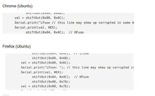
Actually, Erik is right…… in Chrome. It is fine in Firefox. Sorry 🙂
Hmm that is odd, as the line is and was still Serial.print(“LFuse: “); changing that in the same seems very weird. Cannot test it as I dont have chrome and it look sfine in Firefox with me
When i try either of these sketches on an arduino mega 2560, it just shuts down.. I.e. the power LED on the mega stays on, but rest of the LED’s turn off, and there are no further messages coming into the serial monitor.
I build the board to spec, with only one substitution, i substituted the BC547 with an MMBT3904L, and i added a protection diode to the 12v header. (went all SMD)
After the first attempt, i removed the protection diode, and solder jumped the gap, and still the same issue, as soon as i send the character to the serial monitor, the mega2560 simply shuts down.
here’s a link to the board i threw together: https://oshpark.com/shared_projects/AWa0uO8G
Any help would be most appreciated, as i got a couple of fuse-locked digispark clones from ebay, and i’de like to reset them, and reload micronucleus onto them.
lmao.. yea… i need to stop producing PCB’s at 3am.
I spent all day trying to get this to work, including checking, and rechecking again, and again, that the pins are in the correct place on the device, and the arduino, checked the transistor, and swapped it out anyway.. Checked all the resistors, just in case.. Continuity checked the bajeezuz out of the board, and the traces…
JUST NOW noticed, i had inverted the wrong film during production.. The board design shows the transistor on the right-hand side of the board… my board as it on the left-hand side…
Trods off to make a new board.
We all have had screw ups like that. Darn. I hope you will get the proper board soon.
As I only had a few Attiny’s I didnt bother to make a PCB, just used some stripboard 🙂
Goodluck
I understand you found the problem already
I seem to be running into a problem with a bunch of ATTINY85’s I received new from the manufacturer. The fuses are set as 52, 5E, FE and I am completely unable to set them to 62 DF FF. Here is the output of the serial monitor:
Reading signature from connected ATtiny……
Reading complete..
Signature is: 930B
Reading fuse settings from connected ATtiny…….
LFuse: 52, HFuse: 5E, EFuse: FE
Reading complete..
The ATtiny is detected as
ATTINY85..
Writing correct fuse settings to ATtiny…….
Writing complete 62
Writing correct fuse settings to ATtiny…….
Writing complete DF
Writing correct fuse settings to ATtiny…….
Writing complete FF
Fuses will be read again to check if it’s changed successfully..
Reading fuse settings from connected ATtiny…….
LFuse: 52, HFuse: 5E, EFuse: FE
Reading complete..
As you can see, the chip is able to be read but when it comes to the reset and the 12v is applied to the RESET pin nothing changes. My wiring has been quadruple checked, here is the output from my oscilloscope on the
RESET (Yellow) and VCC (Blue) pins: http://pichost.org/image/KbUt
RESET/MISO: http://pichost.org/image/KdVf
RESET/MOSI: http://pichost.org/image/KCh1
That is surprising. The oscilloscope pictures look OK as far as the fact there seems to be a proper 12 Volt level.
The manufacturers settings seem to be a bit odd. May I ask if you got them from a reputable source and if they were really new?
Nevertheles, it seems strange they initially are read as having changed and then later , changed back
I know they are new as they are in the plastic reel and the pins do not have any solder on them under the exam of a microscope. The issue may lie in the procurement from a Chinese ebay seller. Although they have good ratings, they are no Digikey.
Perhaps therein lies my problem.
Well that was exactly why i was asking the question. As their fuses seem to be non standard factory, I was wondering if they were a special -failed- run or maybe rejected in some other form.
That you cannot reset fuses in an entire batch is odd.
The 2N2222 should not be a problem… provided that is of good quality too (I got some 2n2222 duds from china as well)
Just for interest sake you could send me one and I will try but, but the postage might not be worth it
E,
I received a batch of 85’s from Digikey and every one of them was able to set the fuses appropriately. I was even able to set them to the values of the dead batch and back again without issue. However, if you want to shoot me an email at chris@digitaldownpour.org I will send you the ones I was unsuccessful in flashing if you want to take a crack at them. If not I will throw them in the trash.
i will do that
Your serial listing indicates you’re not using one of the two listed programs. Not that I won’t understand if you added some debugging code to it. Adding debugging CAN throw off timing.
My advice at this stage (meaning, not enough info) is:-
– double check if you are using the exact same hardware;
– double check fuse settings of the host Arduino;
– re-try with 100% unmodified code.
I have run unmodified hardware (kinda. It’s a stock 5 volt, so 16 MHz Nano) and unmodified software (2nd script) on ’85s with 100% success.
Thanks Jeroen, had not even noticed that. Very worthwhile comments
Thank you for the advice. Here are my steps taken so far:
-I don’t have a BC547 NPN transistor but I do have a 2N2222. Aside from that, everything else is exactly the same. I attempted it with a 2SC1384 as well as using a P-MOSFET with the RESET line connected to the drain. No luck.
-Fuses on my host Genuine Uno 328P are set to L:FF H:D6 E:FD Lock:CF
After running with the first example of code, unmodified, here is my serial output:
Enter a character to continue
97
Entering programming Mode
lfuse reads as 52
hfuse reads as 5E
efuse reads as FE
Writing hfuse
Writing lfuse
lfuse reads as 52
hfuse reads as 5E
efuse reads as FE
Exiting programming Mode
As these 85’s were purchased from an ebay seller from the place where all quality things flow, China, I am guessing they are DOA. Although they are new, I am wondering if they were pulled from the junk bin, thrown in a reel, and sold to the dumbest American buyer. Which happens to be me along with 55 others.
At some moment you have to to give up and cut your losses, depending how many you got of course. You could be right and these are duds. On the other hand, in my experience these things are like cockroaches. After a nuclear armagedon these critters and the ATtiny’s will be the only survivors. I had several of them fried, but still working when the stupid hardware fault was corrected (try to rotate them in the programmer) 😉
At this moment I don’t think you can do much more than getting your hands on one “known good” and see if those accept the reprogramming. Indeed BC547 vs 2N2222 is 100% irrelevant.
BTW, without wanting to be to anal, that listing is still not from the original. The code does not not print “Writing xxx”. And not printing the writing of the Efuse is probably a leftover of that. I agree it is most probably not the problem at hand.
sir as I’m new to arduino (Beginner) i want to recover my dead attiny85. im little confused about the Sketch uploading, how to upload the program? which board should i select ?(as im using arduino uno for programming) and which clock speed should i select ?
Thanks in advance.
Arna, the uploading is exactly as you would upload any arduino program.
As you are using a uno, that is the board you select and there is no specific clock speed to select
thanks for replying on my comment, as I’m a beginner im scared that i may burn my arduino uno, so im little confused about this problem,but now solved.
I understand, no problem. We all had to begin somewhere
Very insightful. I have packaged the HV Fuse Resetter in a different way here: https://www.instructables.com/id/IOT123-HV-ATTINY85-Fuse-Resetter/
Look good. In fact Ralph also was inspired by my article, but also put his own twist to it
Thanks for your clear explanation ! You save my day !
My pleasure
It worked perfectly! Thanks for sharing and good explanation! Keep this good work
Thank you for your kind words, I am happy it proved useful for you
Can l use MOSFET??
No. A MOSFET works totally different.I strongly suggest you buy the module rather than make the circuit yrself
Apologies, this answer was over a totally different project (an AC dimmer) and thus totally irrelevant
Why would you not use a MOSFET? All this transistor does is switch on and off. You could replace this npn with an n-channel 2N7002 for example. And why not build yourself?
Apologies, I was answering some questions on an AC dimmer and on my phone it is always a bit difficult to see what posting the question relates to, so I erroneously thought your question was about another item (an AC dimmer) where I had just discussed a TRIAC with someone. Then your question came ‘how about a MOSFET’. So my reply was with a different subject in mind. Hence my ‘not to the point answer’
Yes you can use a mosfet, provided it will switch at logic levels.
and best to build it yourself, my earlier reply was again with an AC dimmer module in mind
Thanks for your tutorial,
I took your code and build a simple to use Arduino version available at https://github.com/ArminJo/ATtiny-HighVoltageProgrammer_FuseEraser
Thank you for yr link 🙂
If anyone reads this far. I use Spence Konde’s core, and find the “invalid device signature” results after “burning bootloader” (fuse setting) after deliberately selecting 128KHz is due to the high “Bit Rate” of the programmer, not the baud rate. It can be coped with and fixed by adding -B100 to avrdude switches from the command line for “slow” programming. You may also be able to select a “slow” programmer from the Arduino IDE menu. (leave the bitrate -b 19200? alone – you could try 9600). eg. avrdude -F -D -B100 -c usbtiny -p attiny25 -U lfuse:w:0x62:m -U hfuse:w:0xdf:m -U efuse:w:0xff:m See relevant parts of https://www.ladyada.net/learn/avr/avrdude.html.
Thanks for the info Matthew. I do not know Spence Konde’s core, but your info will surely help someone else with similar problems
Thank You.
My pleasure
Thanks so much for this code – I used the first version on a Tiny85 and it worked first time! I only had a clone Pro Micro board to hand, all I did was change the pin assignment to 4-9 in the code and wiring.
Thanks 🙂
My pleasure. I am happy it helped you
I don’t understand this, schematic shows resistors but breadboard picture does not show any resistors? hope someone can help me, I got a 12v battery just need help with picture and where the resistors go, what are the thin red and black lines are what is U2 ic in the picture diagram, confused.
The picture clearly shows all the resistors. Not sure what pictures you are looking at that wouldn’t show the resistors but they are clearly there. Look for instance at the right side of the stripboard picture there are 5 horizontally mounted resistors. Regardless, when in doubt, follow the circuit. The thin lines are wire connections U2 is the connector. Something tells me you have not build many circuits yet so if you have more questions don’t hesitate to ask. Be careful that you are sure where you connect the 12 volt. It should never come in contact with any of your arduino pins